I was always struggling with how to properly hook up stick welding leads to the welder. Should you connect the ground lead to the welder’s negative terminal or the positive one? Where should the electrode lead go? One can just make things as complicated as he wants.
Many people get confused while understanding the connections of a stick welder. But let me tell you, later I realized that it is not as complex as it seems.
You can connect the welding leads in three different ways called the DCEN connection, DCEP connection, and the AC connection. Each connection has its pros and cons. They should be changed according to the welding application they are being used in.
In this article, I will discuss in detail how to hook up stick welder leads for different welding applications.
Let’s jump right in.
SMAW or stick welding
Shielded Metal Arc Welding, commonly known as stick welding is the most popular form of arc welding. It uses electrical current (usually DC) to melt both the metal workpiece and the electrode rod, forming a weld pool. The electrode is covered with a layer of flux which protects the molten weld from being contaminated by foreign particles (that’s why it’s called Shielded Metal Arc Welding).
Stick welding setup
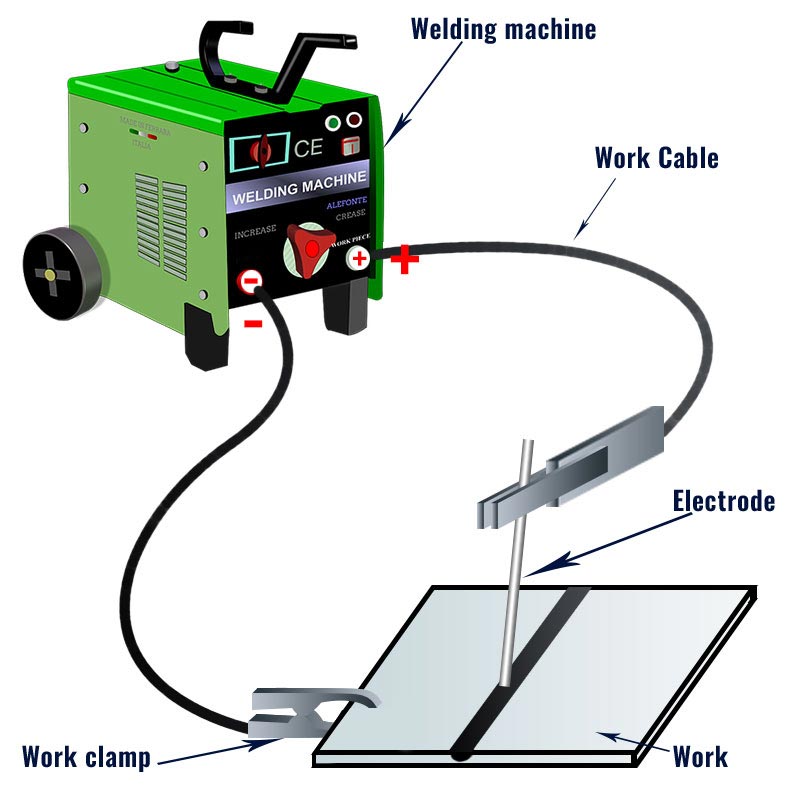
Stick welding setup consists of the following equipment:
- A welding machine
- Welding leads (Work Cables)
- Electrode holder
- Ground clamp (Work Clamp)
- Welding rod (Electrode)
The diagram below shows these components in their proper arrangement.
What are leads on a welder?
Welding leads or welding cables, just like other copper wires, are electrical conductors wrapped inside an insulating rubber jacket. These cables come in different diameters and lengths. For high current applications, we use cables with a large diameter as they offer less resistance to the current. Similarly, for low current applications, you can use the ones with a smaller diameter. It all just comes to the nature of your application.
You have two types of welding leads in stick welding: The electrode lead and the work lead (also called the ground lead). Electrode lead connects our welding machine to the electrode holder. Similarly, the ground lead hooks it up to the workpiece.
Determining welding lead sizes.
Welding leads come in different sizes. While hooking up stick welding leads, you should be extremely conscious about their size. If your cable selection is wrong, you won’t be able to get the desired current and voltage to the welding arc. Consequently, problems like excessive spatter and lack of fusion can occur. Sometimes, if the amperage falls too low, your stick welder simply won’t arc.
The following table shows the correct size of copper and aluminum cables for different stick welding amperage values and lengths of the welding cables.
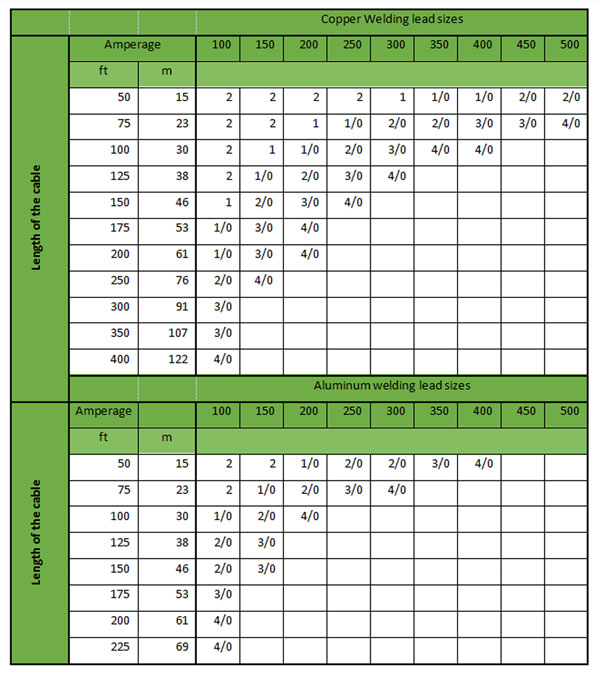
For instance, if your workpiece is about 100 feet away from the welder and your application requires 200 Amps, ask your welding retailer for an aluminum cable of size 4/0 or a copper cable of size 1/0.
Steps to set up stick welding leads
To properly connect the stick welding leads, just follow these simple steps
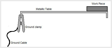
1. Ground clamp placement
First of all, attach the ground clamp at its appropriate position. Ground clamp connects our workpiece to the ground via the work lead. You can either clip it directly to the workpiece or to the metallic table on which your work is to be done (as shown in the figure).
2. Hook up welding leads to the welder
After that, attach the work lead to the negative terminal of the welding machine and electrode cable to the positive terminal. You can also make connections opposite to this depending upon the welding application. Later in this article, I will get to the details of these connections.
Some welding machines have a switch that can be flipped to change the polarity. Otherwise, you have to manually exchange the connections of the welding cables. Before you change the polarity on a welding machine, make sure to turn it off.
3. Plug-in the welding machine
Finally, plug in the machine and switch it on. Set it up to the appropriate current and voltage settings as per your welding application. You are good to go.
Three types of welding setups: DCEN, DCEP, and AC
Many people ask me whether stick welding is a ground positive or ground negative process. The answer to this question is, “BOTH”. In fact, for stick welding, you can hook up the welding cables in three different ways.
1. DCEP welding connection
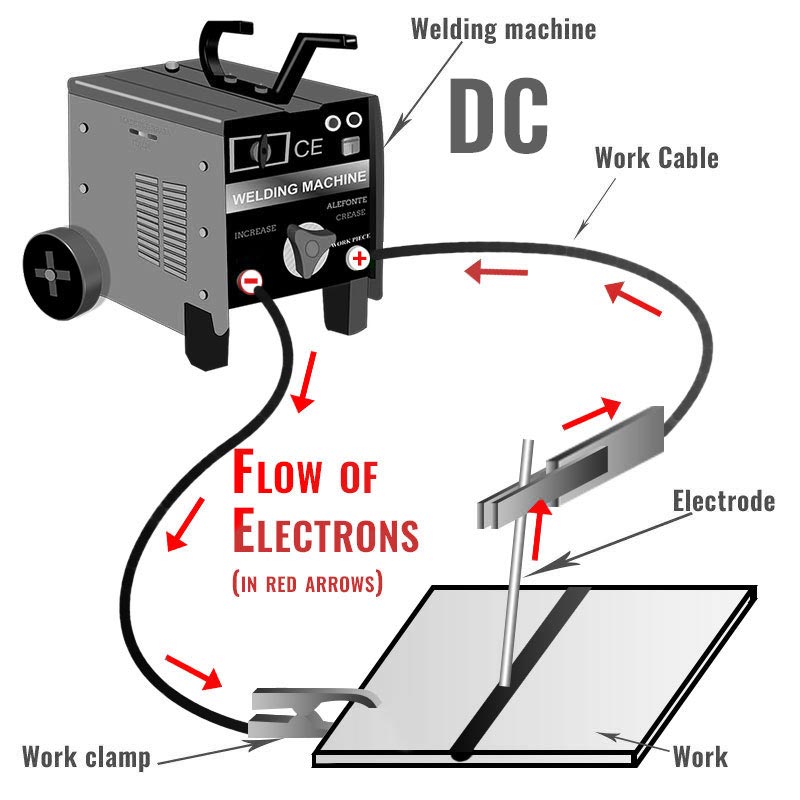
For DCEP or direct current electrode positive connection (formerly known as reverse polarity), you have to connect the electrode holder to the positive terminal and the ground clamp to the negative one. As a result, electrons will flow from the workpiece towards the electrode. For most stick welding applications, we use the DCEP setup. The diagram below shows the setup for the DCEP connection.
2. DCEN welding connection
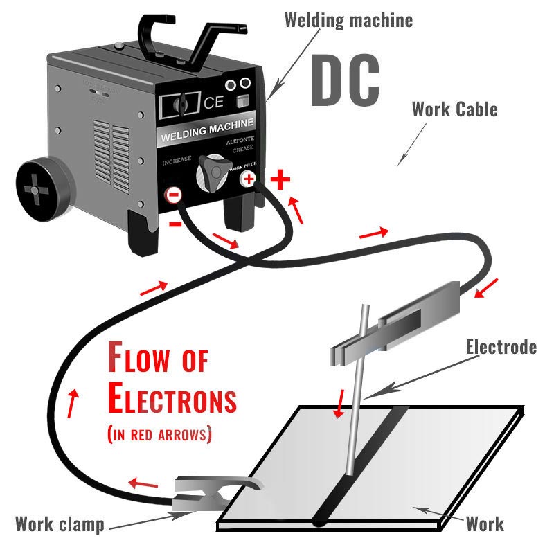
In DCEN or direct current electrode negative (formerly known as straight polarity), the electrode holder is negative and the workpiece is positive. Hence, electrons flow from the electrode towards the positive workpiece. The following figure shows the setup diagram for the DCEN connection.
3. AC connection
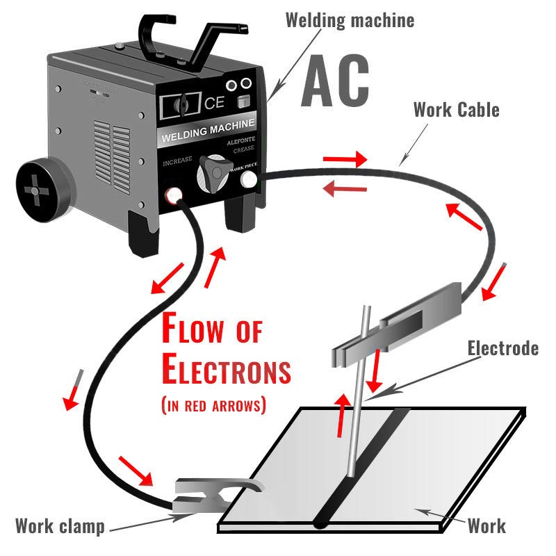
In an AC welding connection, alternating current usually at a frequency of 60Hz is used. The current changes direction every 120th part of a second. Therefore, an AC welding connection has no polarity which results in even distribution of heat between the electrode and the workpiece. Following diagram illustrates the setup for AC connection.
DCEP vs DCEN: What polarity should you stick weld on?
For most of the applications, we hook up the welding leads in a DCEP connection. However, stick welding is quite versatile in terms of polarity.
Keep in mind that electrons always travel from the negative terminal of the welder towards the positive terminal. Therefore, in case of DCEP, the electrons leave the surface of the metal and move towards the electrode because the work lead is connected to the welder’s negative terminal. These electrons after colliding with the positive electrode produce a large amount of heat. As a result, almost two-thirds of the welding heat generates on the electrode and the remaining one-third of the heat accumulates on the workpiece. On the contrary, for DCEN, two-thirds of the heat is formed on the metal being welded because the electrons flow from the electrode towards the base metal.
You can not just randomly choose any welding setup. Each connection has its applications and limitations. Likewise, not all the electrodes work with both DCEP and DCEN.
DCEP, as I mentioned before, produces high heat on the electrode which results in deep penetration. However, the electrode deposition rate in DCEP is low as compared to DCEN. Thus, it is not suitable for welding thin sheets as it may rupture them.
On the other hand, DCEN connection generates less heat on the electrode which provides less penetration. However, the filler metal deposition rate is quite high as compared to DCEP. If you have to weld thin sheets, I suggest you going for DCEN.
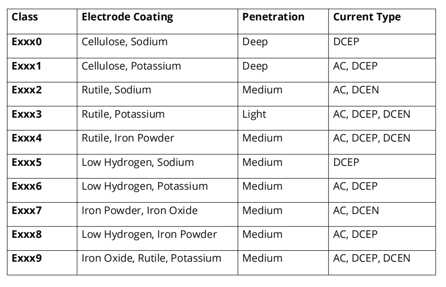
Electrode Selection for different polarities
Different electrodes work best on different current types. Some are good for DC and some for AC. In fact, it depends a lot on the electrode’s coating type. To choose the proper one for your application, the following table might come in handy.
Arc cleaning action in DCEP
One of the main advantages of DCEP over DCEN is its oxide cleaning action.
During arc welding, it is very important to clean the surface of the metal in order to have a good weld. Dirt, rust, oxides and other particles must be removed. Otherwise, these impurities will mix with the molten metal and result in a weak weld.
In DCEP, the avalanche of electrons moves from the base metal towards the positive electrode. This electron stream breaks the non-conducting oxide layer in the metal and inherently removes the contaminated particles from the metal resulting in a strong weld.
AC Welding vs DC welding
Most high power machines run on DC. Some professional TIG and SMAW welders have the ability to run on both AC and DC. But what’s better, AC or DC? If more than 90 percent of the times we use DC, why do we even need AC welding?
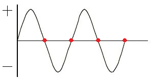
DC welding is quite smooth as compared to AC. Have a look at the following waveform for AC. Each time the polarity switches from positive to negative, there is a moment when the current flowing is zero (see the red marks). Due to this discontinuous flow of current, the arc formed is quite irregular.
However, in some cases, you can prefer AC over DC. One major pro of AC is its arc blow elimination capabilities. Are your welds crooked or wavy? Is there too much spatter around your weld? If “yes”, your weld might be suffering from arc blow. Switching to AC can get rid of such problems. Nonetheless, DC welding has far more advantages than AC.
Stick Welding Troubleshooting for Welding Leads
Prevention is always better than cure. Incorrect usage of welding cables can result in problems like small output current, high resistance, and difficulty in starting arc. Therefore, it is always better to use the appropriate cables and employ the proper welding technique. Still, if some complications arise due to the wrong usage of cables, this small troubleshooting guide might help you do away with these problems.
- Straighten the cables.
- Make sure there are no bends or coils in the cable as it can cause inductance effects in the wires.
- Lower quality cables can cause arc starting problems. Use high-quality cables.
- Use the welding leads of proper size. See the table provided above in this article.
In Summary,
For most of the stick welding applications, you need to connect your electrode lead to the positive terminal and ground lead to the negative (DCEP connection). While hooking up the welding leads, you should exercise extreme caution.
In fact, wrong cable connections can lead to issues like poor penetration, poor filler deposition or arc blow problems. But once you understand the cause, the solution seems quite obvious. Best of luck with your welding ventures.
This was quiet educative, a mastery piece. Thank you
Nice info sharing here. Good job Bro!
I always thought that:
1. DCEN would provide more heat on the workpiece and therefore give better penetration and a flat weld surface
2. DCEP would provide more heat on the electrode and give faster deposition rate and a hump on the weld surface.
Lincoln Electric gives the same information as this article but it seems counter-intuitive to me.
I’m a beginner and I know nothing about stick welding I’m confident that I can set up my machine and start welding. Thank You very informative.
Great site and article; I’ve read every article now. I’m starting a welding class in a few weeks – at 65 years old. I’m looking forward to making and fixing things for myself in retirement. I hope you keep posting and teaching.
Dale
This is Denny Jensen. I just turned 71 live in St. Charles, ID and have much the same interests as you, but have not been successful in finding a school. Can I ask what type of school or institution you found you welding class?
DCEN is used for welding refractory type materials.
Cast iron.
Also there was a thing about generators for welding but I cant recall.
When I started welding we used basic transformers a copper coil with a metal core that you used to adjust your amperage.
No digital read out
It was very educating,as I always confuse the two,very interesting thank you very much.
Hate to admit it but even as an electrician I feel I got a better understanding of frequency when the author said: “ The current changes direction every 120th part of a second “. It had yet to be explained to me that way although I understood how frequency works in an AC circuit. I was able to understand better how frequency affects current because of the break down of just how frequently it is crossing 0° on the X axis
This is another Dale, also just turned 65, and also want to take up more welding! I have a mig welder, now I just bought an old Lincoln stick welder but couldn’t get it to weld – it would just stick, seemed like it was operating on 110V only. I opened it up and found mouse evidence all through it, so figured they had chewed through the cable shielding. I went and bought a different welder. Same thing, it wouldn’t flow! Then I read your articles (https://www.weldingtribe.com/welding-rod-sticking/ and this one), and I’m embarrassed to say it was all operator technique. How to hook up the cables was also confusing, and this article made it so simple. Now, thanks to you, they both work. Very helpful articles for someone who hasn’t touched a stick welder since 1973 in Jr. High!